Click Below on PDF Document to download or print
Literature DC210902 Nortec Commander Silage Facer Side 1
| literature_dc210902_nortec_commander_silage_facer__side_1.pdf | |
| File Size: | 6490 kb |
| File Type: | |
Literature DC210902 Nortec Commander Silage Facer Side 2
| literature_dc210902_nortec_commander_silage_facer__side_2.pdf | |
| File Size: | 4192 kb |
| File Type: | |
Click Below to Start Video
Click Below to Start Video
In Laymen's Terms:
In the silage facer industry. There are Facers that work and Facers that don't. As simple as the design is. Its complicated. End results the farmer is looking for is getting his silage de-faced out of the bunker. He wants a very durable - reliable Facer. A Facer that will leave a smooth face and well processed silage. Processing all types of silage. Rotor stalling has been a industry issue! This issue has been tracked down to rotor tooth air gap. What happens is on tooth will release while the next tooth is entering the silage pile. If this air gap has too much of a distance between teeth it will stall the rotor. Binding, rotor stalling and jamming may occurs.
It has been a common design factor in the industry the longer the tooth the better. Finding out this is actually causing a industry problem. What happens with long tooth design is the tooth is trying to penetrate the silage pile. Trying to remove 6" or more of hard packed silage stalls the rotor. Optimum tooth length is 3". Fact is a 3" tooth will process more silage than a 6" tooth. Tons per hour. There there the Air Gap. Closing the air gap makes for a more of a processing effect then a grab and tear effect.
It has been a common design factor in the industry the longer the tooth the better. Finding out this is actually causing a industry problem. What happens with long tooth design is the tooth is trying to penetrate the silage pile. Trying to remove 6" or more of hard packed silage stalls the rotor. Optimum tooth length is 3". Fact is a 3" tooth will process more silage than a 6" tooth. Tons per hour. There there the Air Gap. Closing the air gap makes for a more of a processing effect then a grab and tear effect.
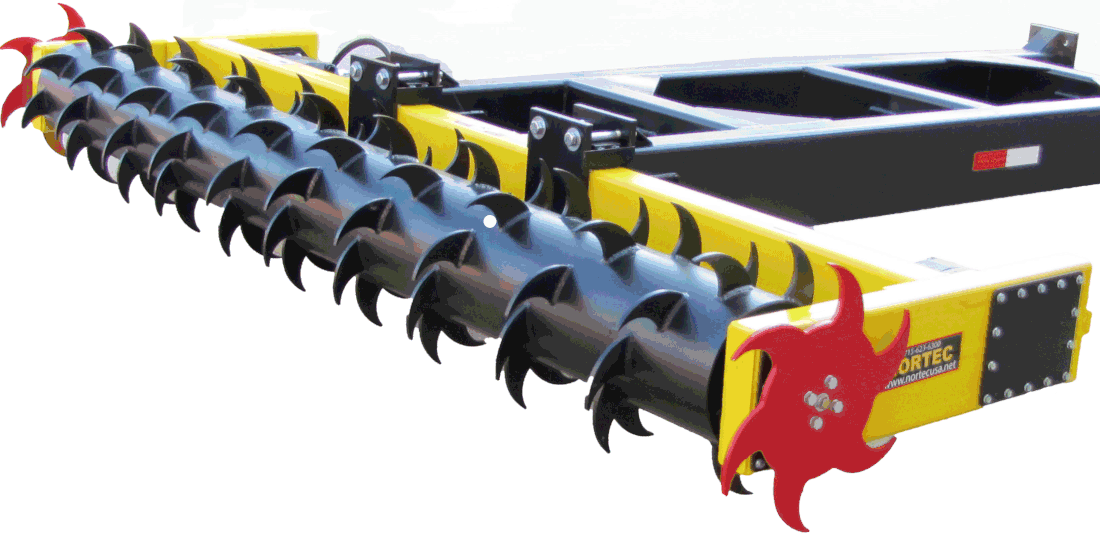
101 Front View
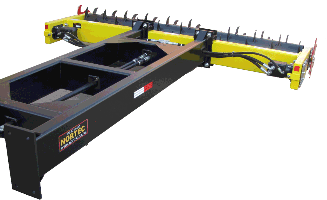
102 Rear View With Boom
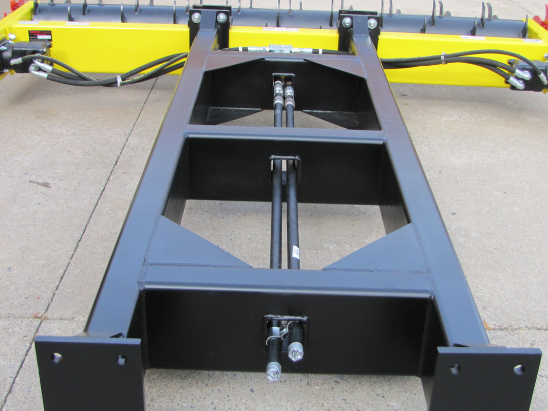
201 Boom's
301 Smart Valve

PSI (Pound Per Square Inch) "POWER"
GPM (Gallons Per Minute) "SPEED"
Basic understanding of PSI and GPM
POWER PSI (Pound Per Square Inch):
Pound per square inch or, more accurately, pound-force per square inch is a unit of pressure or of stress
based on avoirdupois units. It is the pressure resulting from a force of one pound-force applied to an area of one square inch.
based on avoirdupois units. It is the pressure resulting from a force of one pound-force applied to an area of one square inch.
SPEED GPM (Gallons Per Minute):
Pressure Hydraulic oil flow in it's simplest form, is the amount of force that a hydraulic pump can create to move fluid. The other term, GPM or 'Gallons Per Minute' is the scale of measurement used to determine how much hydraulic fluid a tractor will flow in a given amount of time.
Its been an industry problem for years.
Power units such as skid steers, telehandlers and wheel loader manufacturers have been increasing their PSI (Pounds Per Square Inch) and GPM (Gallons Per Minute). Problem # 1 within these different products there is a vast difference in PSI and GPM. Problem # 2 hydraulic motor manufacturers are still stuck in the old method of PSI. It's common 99% of the hydraulic motors are only rated between 2800 and 3000 PSI. Hydraulic motor manufacturers have designed and engineered high GPM motors but have NOT addressed the PSI factor.
Over pressurizing (PSI) the hydraulic motor overtime can lead to CATASTROPHIC hydraulic motor failures. Hydraulic motors are not cheap. Especially if 4 to 6 motor replacements over the lifetime of the attachment / equipment is required.
Over pressurizing (PSI) the hydraulic motor overtime can lead to CATASTROPHIC hydraulic motor failures. Hydraulic motors are not cheap. Especially if 4 to 6 motor replacements over the lifetime of the attachment / equipment is required.
Nortec Smart Valve is the first true advancement in hydraulic motor protection.
Bringing the two product lines together. Prime Movers (hydraulic power source) and the hydraulic motor (supplying power to the attachment).
1) Cross Port Relief
Cross-port relief valves. Function — The cross-port relief valve controls maximum torque of the motor. It provides overpressure protection for the work ports. The cross port relief valve is a full-flow relief. It can bypass all motor flow when pressure reaches the relief setting.
2) Soft Start
These soft start relief valves ramp pressure up from a threshold pressure to the maximum set pressure over a fixed time period, which is slow enough to eliminate virtually all pressure spikes and overshoots.
What happens in real time operation: The owners manual explicitly calls out to engage the hydraulics at idle. What happens in real time is the operator engages the hydraulics at full throttle. This can spike hydraulic pressure up to and possibly over 7000 psi. In times like this it will damage the hydraulic motor creating a huge expense to the owner. Not only in purchasing a new hydraulic motor but also the down time and labor replacement cost.
What happens in real time operation: The owners manual explicitly calls out to engage the hydraulics at idle. What happens in real time is the operator engages the hydraulics at full throttle. This can spike hydraulic pressure up to and possibly over 7000 psi. In times like this it will damage the hydraulic motor creating a huge expense to the owner. Not only in purchasing a new hydraulic motor but also the down time and labor replacement cost.
3) Soft Stop Hydraulic Shut Down
All Prime Mover manufacturers are under strict laws once the hydraulics are shut off. Hydraulic flow must stop in milliseconds. This safety feature protects the operator BUT damages the attachment. What Happens: If an operator shuts down the hydraulics at full pressure (full throttle) this puts a sudden STOP to the hydraulic powering the hydraulic motor. With rotor speed of 175 RPM and then an abrupt lock down, over time will take out the hydraulic motors, chains, sprockets, rotor shafts and lead to damaging of the rotor. Nortec has this problem solved. Smart Valve will automatically bring the rotor inertia to a soft stop.
4) Pressure Relief
Pressure relief valves are used in hydraulic systems to limit the system pressure to a specific set level. If this set level is reached, the pressure relief valve responds and feeds the excess flow from the system back to the tank. Note: the pressure relief valve is a normally closed pressure control valve.
5) Case Drain
Often in hydraulic systems, hydraulic motors and pumps run case drain hoses. The reason for this is to drain excess internal oil leakage from the motor. This is certainly critical in hydraulic motors which have some internal leakage. After having several reported failed motors due to shaft seals leaking, hydraulic motor manufacturers suggested using case drains. It meant quite a bit of extra work and materials (hoses, brackets, fittings etc.) to return the oil back to tank but since then the problem has been eliminated. NOTE: Case drain is an option on some hydraulic motors. Same holds true for the Prime Mover. As simple and effective as case drain is., it can be very complicated.
How if Works: As stated earlier the hydraulic motor must be equipment with case drain. The hydraulic motor case drain is plugged from the hydraulic motor manufacturer. At this point the customer can elect to use case drain or not. If a customer elects to use case drain it's as simple as removing the case drain plug and installing a 1/4" hydraulic hose. Better known as a bleed off line. Run the bleed off line back to the Prime Mover. The 1/4" bleeder hose then has a small 1/4" Pioneer Hydraulic Coupler. Attention: Some manufacturers have a male Pioneer Coupler and other offers a female Pioneer Coupler. Caution: The Prime Mover may not have case drain hose and couplers installed. In this case you need to contact the Prime Mover dealer you purchased the Skid Steer, Telehandler or Wheel Loader from and order a case drain kit. NOTE: Nortec has encountered on several occasions Wheel Loader manufacturers who do not offer a case drain option. In this case the dealerships service technician can install a case drain kit.
Now you have the case drain installed. What does it do? Case drain line will relieve any excess pressure and drain it back to your return line, then into the hydraulic oil reservoir on the Prime Mover. Note: it is not uncommon for the small case drain hydraulic line to feel hot at the touch. This means the case drain is doing it job. Also note, you may encounter case drain hose jumping. This is common. The case drain valve on the hydraulic motor is opening and closing to relieve excess pressure.
The downside of the upside on case drain. If your Prime Mover already is case drain equipped, you are good to go. All you need to do is run a 1/4" bleeder line from hydraulic motor to prime mover. If not, it can be a struggle getting your prime mover equipped with case drain. Nortec's new Smart Valve has your back along with cutting down on your level of frustration. The case drain is designed and engineered into the Smart Valve. The bleeder hose NOW is routed into the Smart Valve. Good new does not stop here! This method cuts down on having to install and remove the case drain hose. You're protected without the hassle of another hose connection. Also, there is a great possibility that little additional 1/4" bleeder connection hose may get damaged if snagged.
Case Drain Port: Standard Equipment
High case pressure cause the oil to press on the backside of seals causing the lip to wear a groove in the shaft and eventually the seal will totally fail. This is pressure on the back side of the seal which is not designed to handle pressure. Case drains are designed into pumps and motors to route this slippage/seepage oil from the back side of seals and pistons and allow the oil to return to the reservoir under minimal pressure.
If you were to route this oil into the return line (which has some pressure in the line do to restrictions) you have now pressurized the back side of the seals. This would be much worse if you were to reverse the hydraulic flow (by accident of course) since the return line is now the pressure line and you would now put over 3000 psi of pressure into the case drain pressurizing the back side of the seals with immediate seal blowout.
If you were to route this oil into the return line (which has some pressure in the line do to restrictions) you have now pressurized the back side of the seals. This would be much worse if you were to reverse the hydraulic flow (by accident of course) since the return line is now the pressure line and you would now put over 3000 psi of pressure into the case drain pressurizing the back side of the seals with immediate seal blowout.
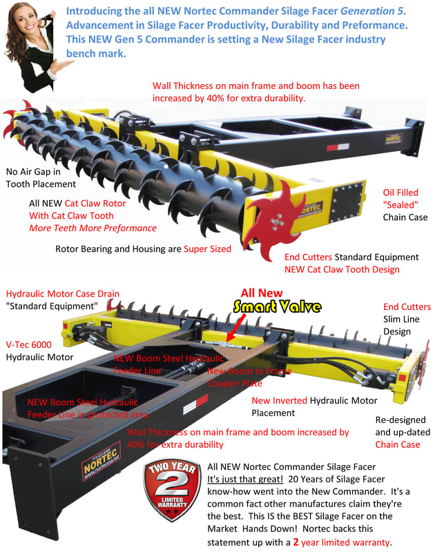
301 All NEW Cat Claw Tooth and Rotor

The rotor is the foundation of all Silage Facers. Many factors go's into designing a rotor. Processing and removing the silage, low horse power requirements, efficient. Nortec Engineering went threw great struggles and sleepless nights coming up with the perfect tooth design and placement.
Teeth are strategically placed for optimum performance. NO AIR GAP

Cat Tooth end rotor clean out tooth placement. Highlighted in RED.
To prevent silage build up on the end rotor, next to the chain case. Extra teeth are position to do a circle clean up. Efficient silage processing.
To prevent silage build up on the end rotor, next to the chain case. Extra teeth are position to do a circle clean up. Efficient silage processing.
Massive 2" Rotor Shafts
Air Gap
Many factors go's into designing a rotor. Processing and removing the silage, low horse power requirements, efficient. Nortec Engineering went threw great struggles and sleepless nights coming up with the perfect tooth placement. Knowledge is powerful. One key factor we have discovered is Air Gap. What is Air Gap and why is it a issue. Air Gap is the distance between on tooth in relationship to the next tooth. So many factors enter into tooth placement. The tooth entering the silage pile and making the primary cut. Followed the the side tooth, followed up with the next up tooth entering the silage pile. This all happens in mill-a-seconds.
Tooth Configuration: Teeth are tipped forward, rather than being perfectly in line with the center of the rotor. This is called "hook angle." Rotor tooth has a positive hook angle, the teeth are tipped forward, toward the direction of the blade's rotation. A negative hook angle means that teeth tip away from the direction of rotation. Hook angle has an important effect on rotor operation. Negative hook angle will slow the feed rate and will also inhibit the rotors tendency to "climb".
Tooth Gullet: The gullet is the space in front of each tooth to allow for silage removal. The feed rate is faster, so the gullet needs to be deep enough for the large amount of silage material it has to handle. The gullets of a combination teeth are designed to handle both processing and crosscutting of silage material.
Tooth Placement: Wear Rotation of the rotor causes the silage to move out of the bunker. To reduce bounce, there are always on teeth in contact with the silage bunker. The special design cork screws the tooth into the silage pile. Relief angle to reduce tooth drag for added power.
Silage Saver Tooth Design: Hollow ground for cutting performance. Unlike a stright or angled tooth this silage saver tooth design will not reduce partical reduction.
Tooth Material: Wear and impact resistant steel. Nortec's Cat Claw tooth is a AR material. Very much like the material used in plow blades. It’s a abrasion resistant steel. Mixture of Boron, Manganese, Nickel, and Chromium to make it wear resistant.
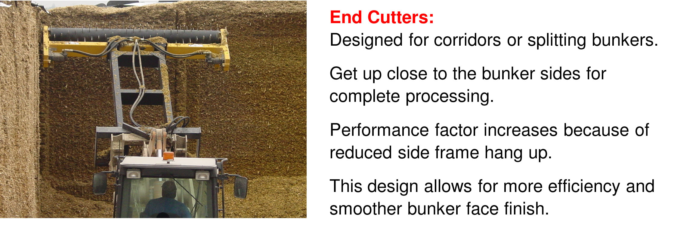
302 End Cutters are now STANDARD EQUIPMENT
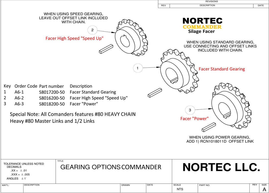
Re-Gearing
Having a chain case offers tremendous advantages. One of the advantages over direct drive is re-gearing. The Commander is designed for a wide range of power units, skid steers, telehandlers and wheel loaders. There is a wide range of GPM specification for engineering to address. Engineering took the middle of the road with a happy medium approach. Let's address the speed. Higher GPM means speed for some farmers and they feel the rotor is too fast and feed damage may occurred. Too slow of rotor speed means more time facing. Nortec solved this problem because of our chain drive. It's as simple as changing a sprocket. Then there's power gearing. Installing this gear package will offer lower speed... BUT MORE POWER. Then there is another factor, Farmer / Operator preference. Talk to 10 different operators and you get 10 different operating conditions. Some operators feel low speed is the way to go. Others feel speed results in faster silage facing. No worries, we got you covered!


